Flexible Shaft Couplings
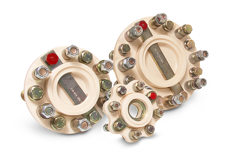
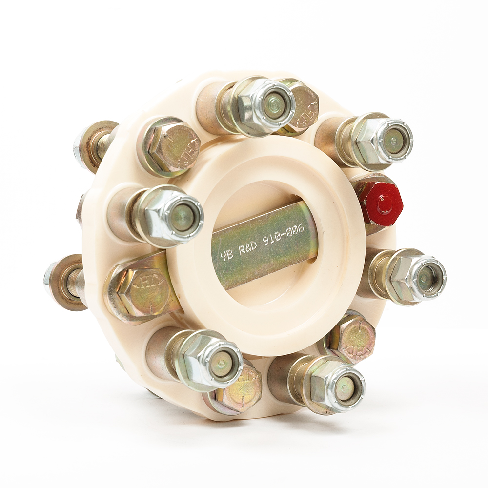
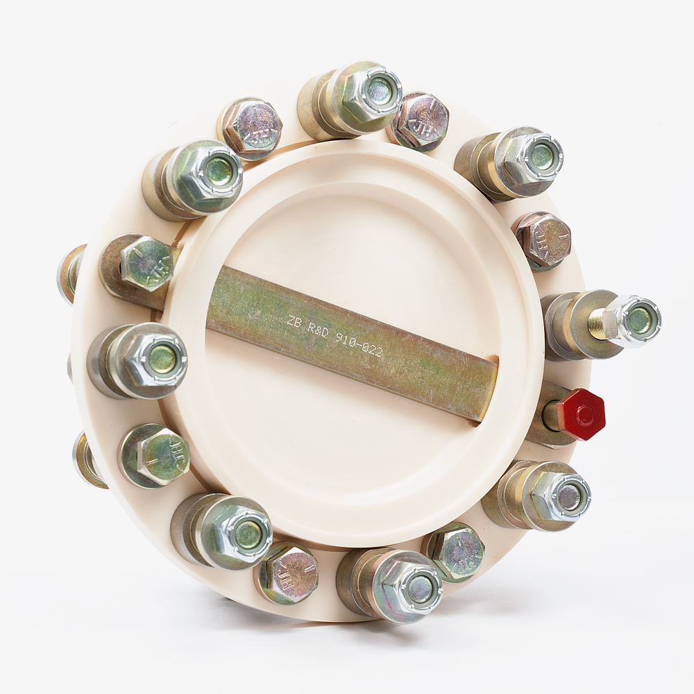
The R&D Marine Flexible Coupling fits between the transmission output flange and shaft coupling. It is designed to protect a boat's drivetrain. The unit will reduce vibration, compensate for some misalignment, isolate the shaft and absorb shock loads.
The flexible disc is machined from a resilient and durable polyurethane. It allows the unit to flex, absorbing vibrations and temporary misalignment of the shaft and engine due to movement of the engine or flexing in the vessel's structure.
The polyurethane disc is backed up by two metal compression straps, one on either side of the flexible coupling. These metal straps hold the system in constant compression whether the drivetrain is in forward or reverse. This feature extends the life of the system dramatically.
The R&D Marine Flexible Coupling will also absorb shockloads resulting from gear changes, or the propeller striking a submerged object. The polyurethane disk will distort with light shock loads and is designed to be sacrificial in the event of severe shock load, saving on expensive drivetrain repairs. If the disc is destroyed from massive shockload the metal compression straps keep the coupling intact ensuring that the drive system is functional in both forward and reverse.
Reduce Noise & Vibration
Staggered bolts enable the polyester elastomer to isolate vibrations and compensate for some misalignment.
Avoid Damage
Absorbs transmission shock load caused by the propeller and high speed gear changes. This helps to reduce and avoid costly transmission damage.
Fail Safe Design
Two steel straps prevent drivetrain from separating in the event of a severe impact. The aft steel strap is bolted to the transmission coupling and the forward steel strap is bolted to the shaft coupling. The aft strap will engage the forward strap and keep the drivetrain together if the elastomer is damaged.
Quick & Easy Installation
Requires no machining and comes supplied with bolts to connect between two existing shaft flanges.
Flexible Shaft Coupling Installation Instructions
- Roughly align engine and stern gear without flexible coupling i.e. only two rigid half couplings pushed together.
- Bolt the R&D Marine coupling between the two rigid couplings. Tightening details as below.
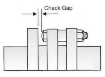
- Check alignment of the engine by placing feeler gauges between the Red Cone Headed Bolt and the rigid half coupling. Repeat for the Same bolt at 90 degrees intervals by rotating the shaft.
- If the gap is the same in all four positions, the engine is accurately aligned. Recommended minimum to maximum gap difference 0.010 inch/ 0.25 mm.
- Run installation to bring engine compartment to working temperature. Re-check torque settings.
Recommended Torque Settings
| 3/8 UNF | 30 ft lb (40Nm) |
|---|---|
| 7/16 UNF | 60 ft lb (81Nm) |
| 1/2 UNF | 75 ft lb (100Nm) |
| 5/8 UNF | 155 ft lb (210Nm) |
| 3/4 UNF | 270 ft lb (366Nm) |
| M10 | 45 ft lb (61Nm) |
| M12 | 80 ft lb (108Nm) |


